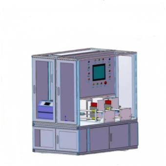
Laboratory Prismatic Battery Helium Filling and Sealing Pin Insertion Machine
1、 Equipment Overview
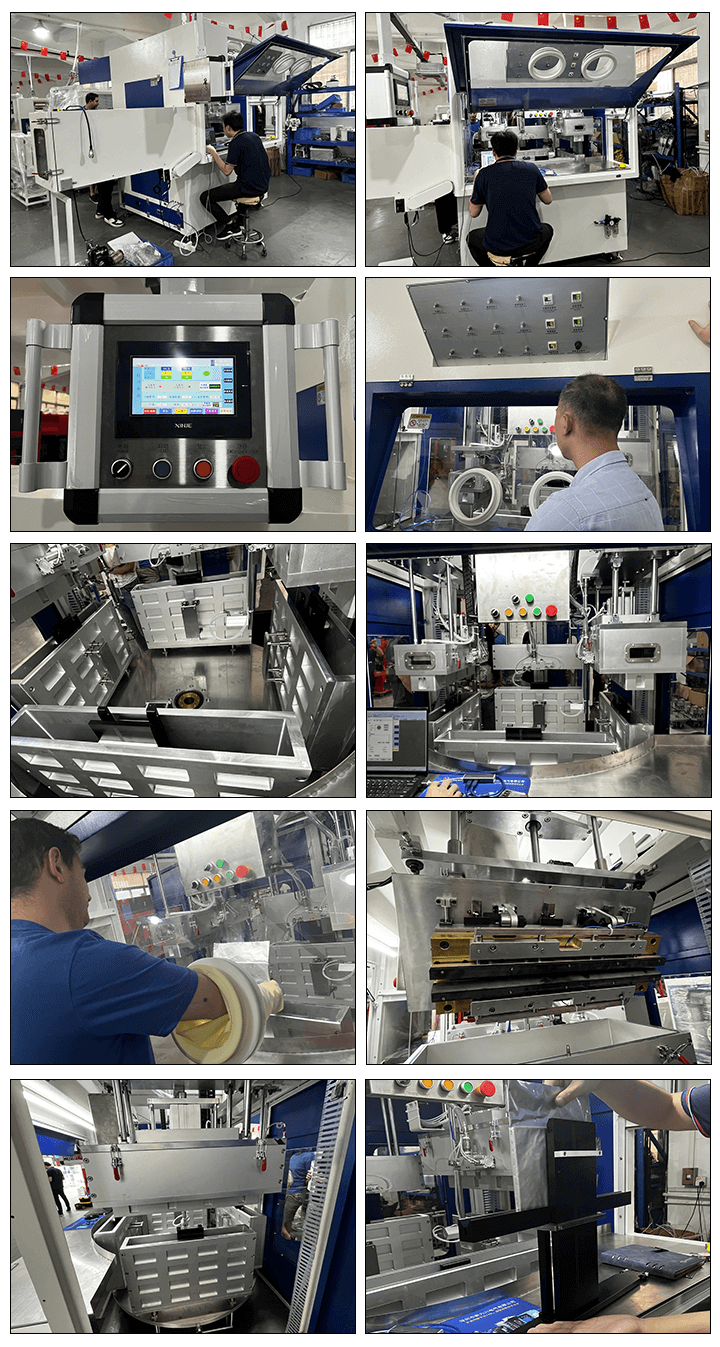
Function Description
This machine is a helium filling and seal pin insertion device that uses a negative pressure pumping mechanism, a helium filling mechanism, a pneumatic nail pressing mechanism, and a cell positioning mold seat mechanism. It is manually fed with batteries, pre pressed glue nails, vacuumed, helium returned, and fully pressed glue nails, and then manually visually inspected for manual cutting.
Manually align the battery cell hole with the upper needle and install it into the fixture for positioning. Push the fixture with the battery into the liquid injection station for positioning, and the foot pedal will collapse to automatically inject liquid. After the liquid injection is completed, it will automatically shift to vacuum static absorption (the vacuum static absorption can adjust the time, vacuum pressure, and absorption frequency). After the static absorption is completed, the battery fixture will automatically push out the battery fixture and manually remove the battery.
2.1 Workflow
1. Workflow Overview
Manual insertion of batteries - fixture clamping and positioning - sealing mechanism for injection holes for downward pressure - vacuum pumping and pressure maintaining - helium charging - pneumatic pressure glue nails - measurement mechanism resetting, fixture loosening - battery removal (sealing glue nails are prefabricated on the injection hole)
2、 Product Blueprint Information
3.1 Product incoming material information
|
No
|
Height(mm)
|
Thickness(mm)
|
Width(mm)
|
|
1
|
200~650
|
10~40
|
70~130
|
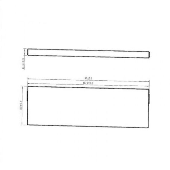
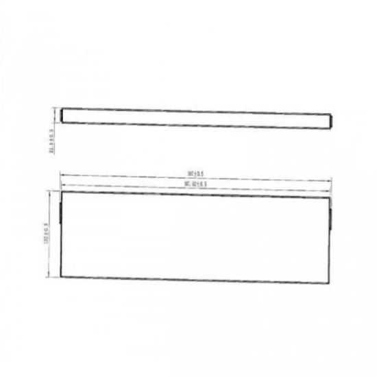
3.2 Blueprint Information
|
No
|
Height(mm)
|
Thickness(mm)
|
Width(mm)
|
|
1
|
501.92±0.3
|
21.5±0.3
|
122±0.5
|
4.1 Equipment Requirements
|
No
|
Item
|
Technical parameters
|
Note
|
|
1
|
Size
|
L800mm*W600mm*H1750mm
|
/
|
|
2
|
Weight
|
1T
|
/
|
|
3
|
Maximum size of a single packaging
|
L800mm*W600mm*H1750mm
|
/
|
|
4
|
Maximum weight of a single packaging
|
1T
|
/
|
|
5
|
Load bearing capacity of transportation channel
|
1T/m2
|
/
|
|
6
|
Electricity consumption
|
2KW
|
/
|
|
7
|
Common nitrogen (m3/h)
|
/
|
Pressure:/
Dew point:/
|
|
8
|
High purity nitrogen (m3/h)
|
/
|
Pressure:/
Dew point:/
|
|
9
|
Cooling water (m3/h)
|
/
|
Temperature:/
Pressure:/
|
|
10
|
Pure water (m3/h)
|
/
|
/
|
|
11
|
Process exhaust (air volume m3/h, wind speed m/s, air pressure Kpa)
|
/
|
Temperature:/
Type:/
|
|
12
|
Process air intake (air volume m3/h, wind speed m/s, air pressure Kpa)
|
/
|
Temperature:/
Type:/
|
|
13
|
Dust removal and exhaust (air volume m3/h, wind speed m/s, wind pressure Kpa)
|
/
|
Wind speed:/
|
|
14
|
Compressed air (m3/h)
|
10
|
Pressure: 0.6MPa
|
|
15
|
Vacuum (m3/h)
|
10
|
Pressure: -90KPa
|
4.2 Application Environment Requirements
1) Environmental temperature: 25 ± 5 ℃.
2) Humidity: 5%~55%.
3) There are no corrosive gases, liquids, or explosive gases on site.
4) Altitude: ≤ 2000m.
5) Power supply voltage: 3/N~50Hz/TN-S (low-voltage distribution system), 220V ± 38V. Frequency 50Hz ± 1Hz.
6) Lighting, HVAC, and public facilities comply with relevant regulations and user requirements.
7) The load-bearing surface of the liquid injection machine area should bear a weight of ≤ 1500kg/㎡.
8) Workshop grounding resistance ≤ 10 Ω.
4.3 Civil requirements
According to the mechanical industry standard JB/T 9018-1999, buildings should meet the following requirements:
1) Ground tolerance: The flatness within the full length range should comply with the requirements of FEM9.831 (European Machinery Handling Association), as follows:
|
Room length/m
|
Full length flatness of the ground/mm
|
|
≤50
|
±10
|
|
≤150
|
±15
|
|
>150
|
±20
|
2) Under the long-term maximum load, the uneven settlement of the equipment area foundation shall not exceed 1/500, and there shall be no seepage or water accumulation.
3) The allowable deviation of the room floor is ± 10mm, and at any 3m × Within a 3m area, not exceeding ± 3mm.
4) The liquid injection workshop has an average static load of about 1.5T/m2 on the ground and a dynamic load of about 1.8T/m2.
4.4 Lighting requirements
Good lighting is required in the work area, and Party A is responsible for lighting.
4.5 Grounding
1) To ensure the safety of equipment and personnel, all equipment must adopt grounding protection, with a grounding resistance less than 4 Ω. If the same grounding network is used for electrical grounding and building lightning protection grounding, the electrical grounding point cannot be directly connected to the building lightning protection grounding down lead, and sufficient distance must be ensured according to regulations. Areas such as insulation testing, liquid injection, charging and discharging shall be pre embedded with anti-static piles according to requirements.
2) In order to prevent the occurrence of dangerous high voltage during insulation damage or aging of electrical equipment, the metal casing of electrical equipment that is not charged under normal circumstances should be grounded.
3) Most of the cables and wires in this system are routed inside or on the equipment, while the rest should be laid inside the cable tray.
4、 Technical requirements for helium filling and sealing pin insertion machine
5.1 Core indicators
|
No
|
Item
|
Index
|
Note
|
|
1
|
FPY (First pass rate, defects caused solely by equipment reasons)
|
≥99%
|
/
|
|
2
|
Failure rate (only caused by equipment failure)
|
≤2%
|
/
|
|
3
|
MTTR (Fault Repair Time)
|
≤60min
|
/
|
|
4
|
Production rhythm/efficiency
|
Helium Filling&Seal Pin Insertion Machine ≥1PPM
|
/
|
|
5
|
MTBF (Mean Time Between Failures)
|
≥4H
|
/
|
|
6
|
Model switching time (including debugging)
|
a) The time to switch between models that have already been produced is less than 4 hours per person per unit.
b) The time to switch between models that have not been produced is less than 6 hours per person per unit.
|
/
|
|
7
|
CMK
|
≥1.67
|
/
|
5.2 Technical requirements for sealing pin insertion module
5.2.1 Function Description
This module is suitable for pre punching glue nails on the liquid injection holes of batteries, vacuuming and helium filling full pressure glue nails, and detecting the position of glue nails.
5.3 Downward pressure suction negative pressure and inflation detection mechanism
5.3.1 Technical requirements for downward pressure, negative pressure, and inflation detection mechanisms
|
No
|
Mechanism
|
Technical requirements
|
|
1
|
Downpressure suction negative pressure and inflation detection mechanism
|
Function Description
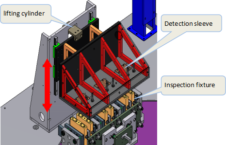
1. After pre pressing, the suction needle extracts the vacuum degree of the battery to the set value, and then recharges helium into the battery. After the inflation reaches the set value, the secondary pressure nail compacts the adhesive nail.
2. The driving mechanism of the pressing nail ensures that the depth of each pressing is consistent, and can only perform limit and height detection;
3. The thickness of the positioning limit during the insertion process is adjustable, and the insulation design of the part in contact with the battery is fully wrapped in the battery cell mode;
4. After sealing, all the glue nails are pressed into the injection hole, with a flat surface and no indentation on the appearance of the injection hole. The sealing with the injection hole is good, without air or liquid leakage. The process vacuum and helium pressure are both displayed with digital precision measurement.
5. After full pressure nail sealing, it is equipped with sealing testing.
Indicator accuracy
1. Vacuum range -100Kpa~0Kpa.
2. Helium filling cut-off pressure range: vacuum degree~50Kpa.
3. The glue nail exceeds the liquid injection hole by ≤ 0.2mm, and the diameter of the glue nail after flattening is less than 5mm.
Safety
1. Positioning with battery overvoltage protection function.
2. After helium return, the residual liquid tray is cut in to receive the residual liquid generated by helium return.
Maintenance
1. The oil filling port of the nail pressing mechanism should be designed upwards, with a reserved oil filling space of ≥ 100mm, which is convenient for adding lubricating oil.
Replacement of a product
1. The nail pressing mechanism can be linearly adjusted, and parts do not need to be replaced when changing types (except for glue nail models).
Contamination control
1. The contact area with the battery is made of non-metallic, wear-resistant, and corrosion-resistant materials.
|
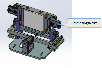
5.3.2 Technical requirements for cell positioning mechanism
|
No
|
Mechanism
|
Technical requirements
|
|
1
|
Cell positioning device
|
Function Description
1. After manually placing the battery cell into the fixture and positioning it
2. Accurate and reliable positioning and pinning, and the positioning mechanism must ensure that the battery does not shake during the pinning process.
3. The fixture is compatible with battery cells of different sizes and specifications, requiring manual adjustment of the fixture;
4. Manually judge the appearance and size of the placed battery cells, and eliminate unqualified products;
5. Features and functions: The transmission structure is simple and stable, preventing scratches and pressure damage to the pole pieces.
|
5.4 Other accessories
5.4.1 Technical requirements for other accessories
|
No
|
Mechanism
|
Technical requirements
|
|
1
|
Other accessories
|
Function Description
1. Main materials: SU304 stainless steel plate and square tube are used, the vacuum box is made of aluminum alloy for oxidation treatment, the load-bearing part of the rack is made of 40mm * 40mm aluminum profiles, the bottom plate is made of 12mm aluminum plates, and the upper part is made of aluminum profiles+PC plates;
2. Glass and glove ring: 6mm imported transparent PC board is used for Glovebox glass, and the transparent PC board is made of aluminum alloy profile frame and fastened with screws. The glove ring is made of anti-corrosion materials, and the glove ring and sealing ring are installed on the transparent PC board;
3. Long arm gloves, foot cups, and casters: The reserved operation station gloves are made of acid and alkali resistant long arm gloves, with 1 pair (total of 2) as standard, and 4 foot cups and casters each. After the equipment installation is completed, they will be positioned.
4. The equipment is equipped with a safety light curtain alarm;
5. NG products have alarm prompts and counting functions
|
6、 List of equipment components
|
No
|
Name
|
Brand
|
Qty
|
Note
|
|
1
|
PLC
|
Inovance/Panasonic/Omron/Dalte
|
1 set
|
/
|
|
2
|
man-machine interface
|
Weinview/MCGS
|
1 set
|
/
|
|
3
|
servo system
|
Yako/Dalte/Yaskawa
|
1 set
|
/
|
|
4
|
Stepper driver
|
Yako/LeadShine/yaskawa
|
3 units
|
/
|
|
5
|
Stepper motor
|
Yako/LeadShine/yaskawa
|
3 units
|
/
|
|
6
|
Single head variable displacement pump
|
CHUANG TAI
|
1 unit
|
/
|
|
7
|
Vacuum valve
|
NANVA
|
6 sets
|
/
|
|
8
|
Injection shaft
|
/
|
1 set
|
/
|
|
9
|
Customized liquid storage cup
|
/
|
4 sets
|
/
|
|
10
|
Absorption tank cylinder
|
STNC/AirTAC
|
2 sets
|
/
|
|
11
|
Disk moving cylinder
|
STNC/AirTAC
|
1 set
|
/
|
7、 Random gift items
7.1 Random delivery materials
|
No
|
Name
|
Qty
|
Note
|
|
1
|
Equipment operation and maintenance manual
|
1
|
1 electronic file and 1 paper file
|
|
2
|
Equipment Maintenance Manual (with illustrations)
|
1
|
1 electronic file and 1 paper file
|
|
3
|
Certificate of conformity for main standard components of equipment
|
1
|
1 electronic file and 1 paper file
|
|
4
|
List of Vulnerable Parts
|
1
|
1 electronic file and 1 paper file
|
|
5
|
Pneumatic/hydraulic schematic diagram
|
1
|
1 electronic file and 1 paper file
|
|
6
|
Instructions for Main Outsourced Components of the Equipment
|
1
|
1 electronic file and 1 paper file
|
|
7
|
Drawing of vulnerable parts
|
1
|
Provide a list and part code, one electronic file; The vulnerable parts of logistics equipment are mostly standard parts, with models provided. The fixture vulnerable parts of the robotic arm are provided with part processing drawings
|
|
8
|
Equipment BOM (raw material) list, including brand and model of cables, signal wires, etc
|
1
|
1 electronic file and 1 paper file
|
7.2 Equipment random items
Vulnerable parts:
|
No
|
Name
|
Qty
|
Note
|
|
1
|
sealing ring
|
10
|
Circular Ø 16
|


 en
en fr
fr de
de ru
ru es
es pt
pt ko
ko tr
tr pl
pl th
th


 IPv6 network supported